Week 0 (Nov 11 - Nov 13)
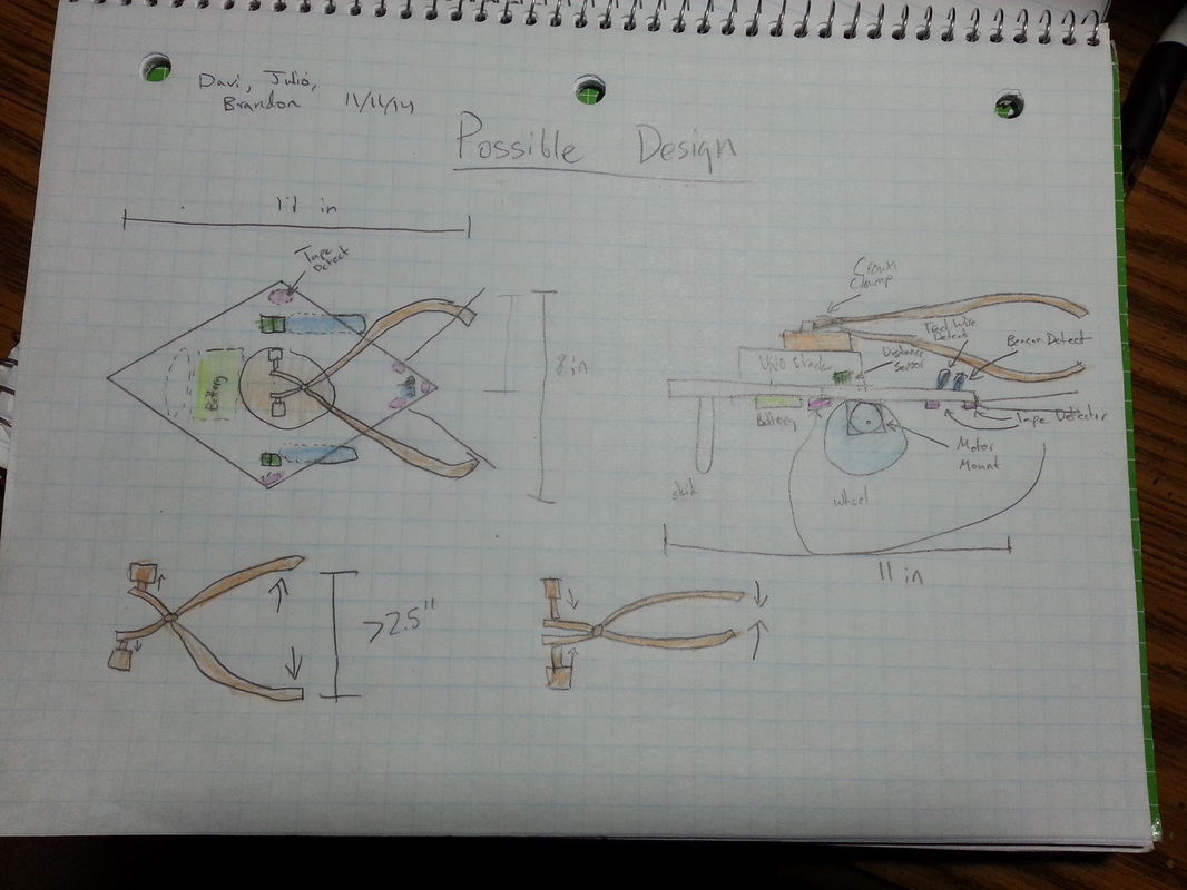
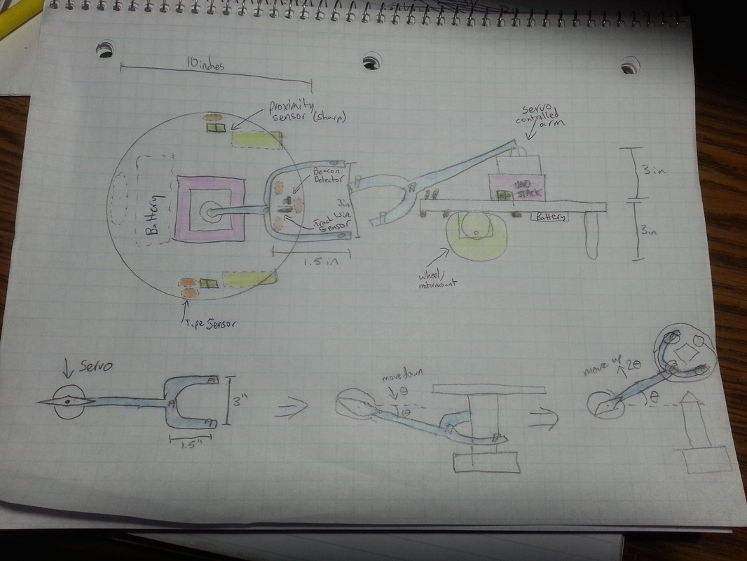
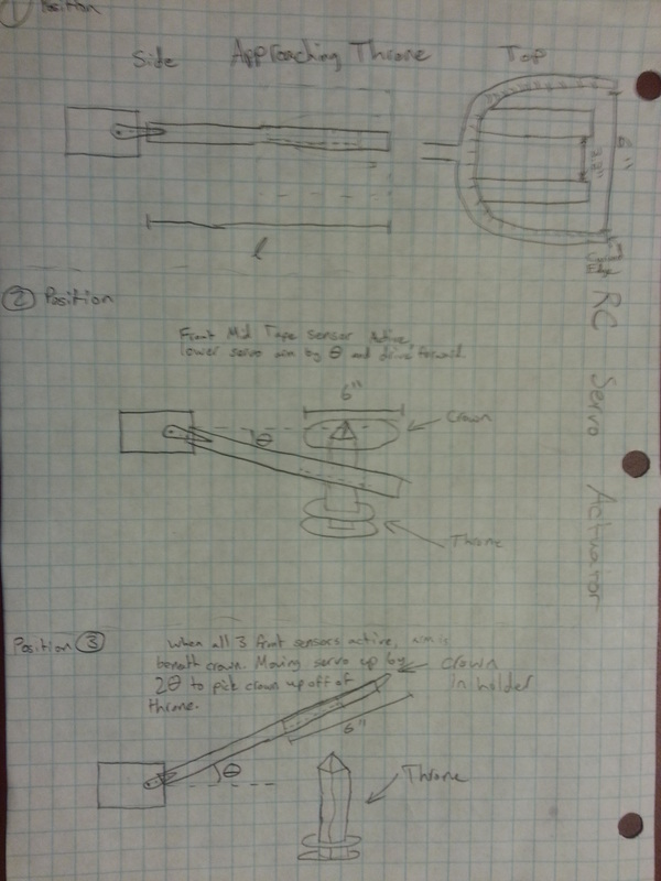
Initial Robot Designs
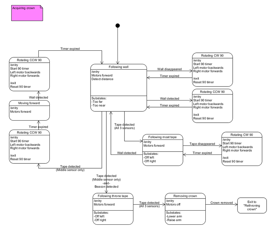
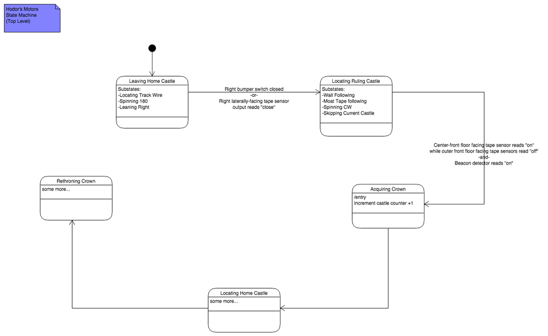
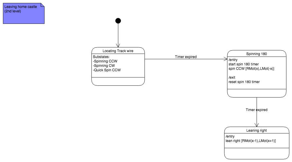
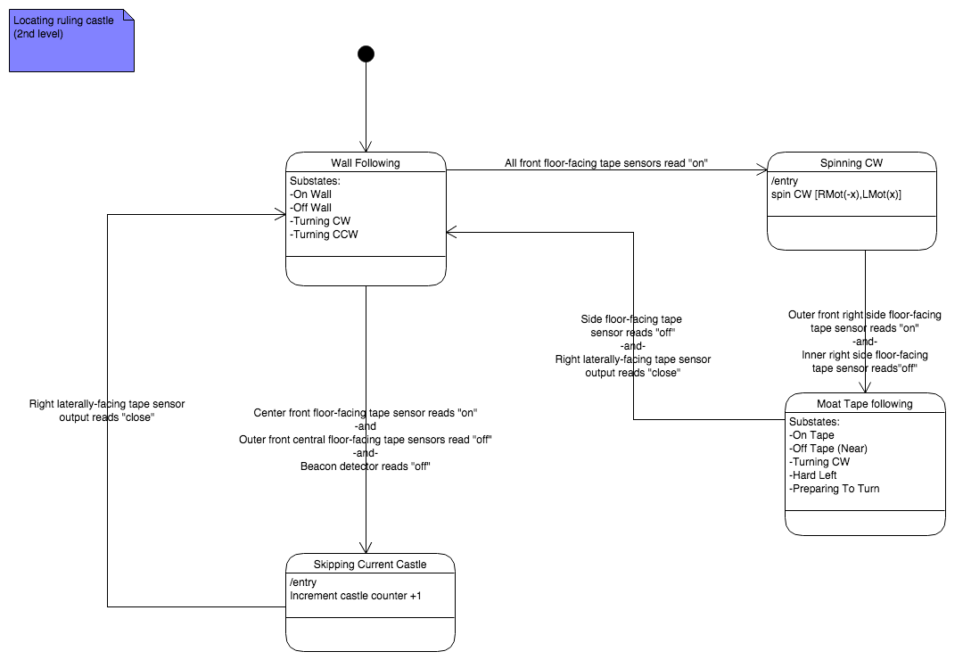
Initial State Machine Designs
Week 1 (Nov 14 - Nov 17)
System Block Diagram (for checkoff)
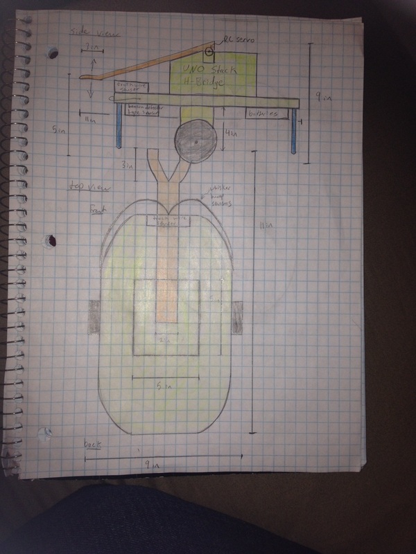
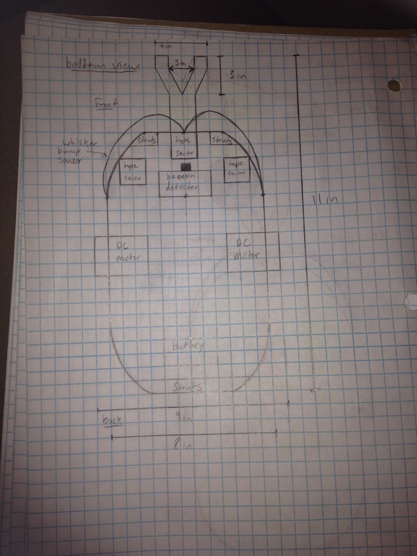
Updated Design Sketches
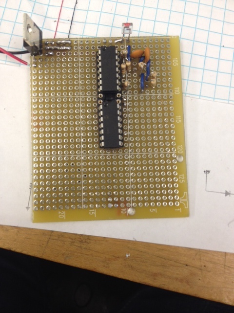
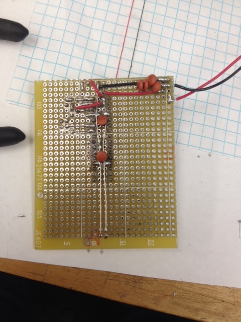
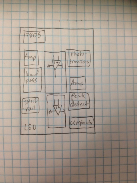
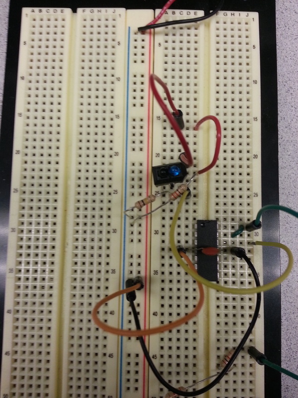
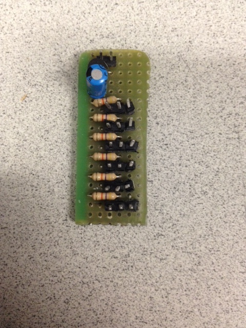
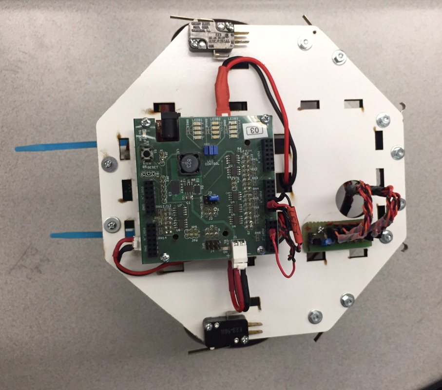
Beacon Detector Schematics
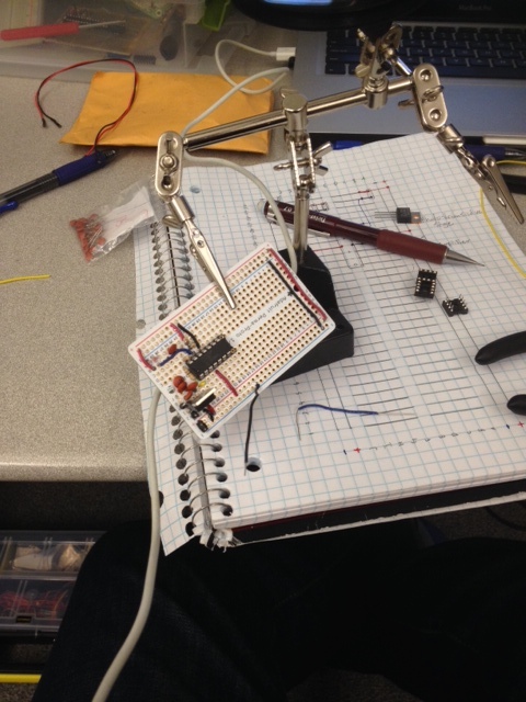
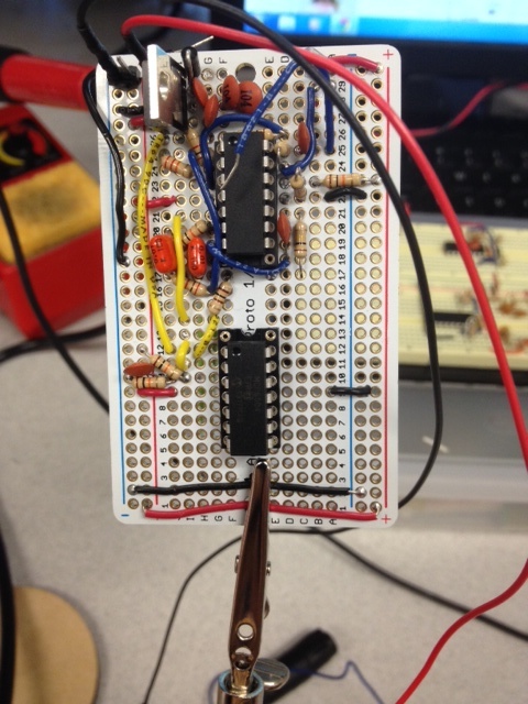
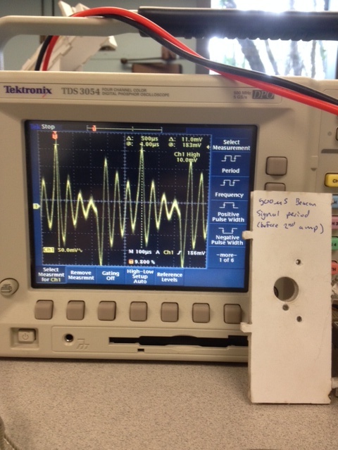
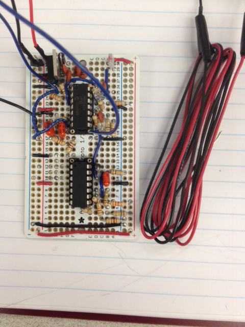
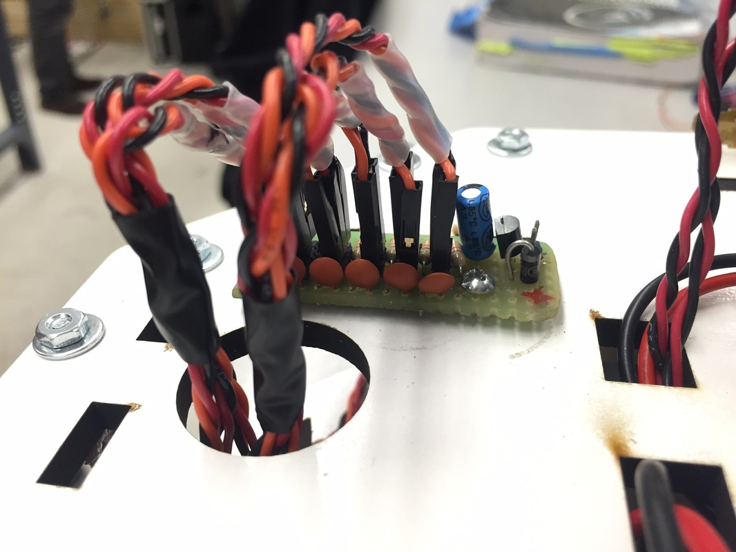
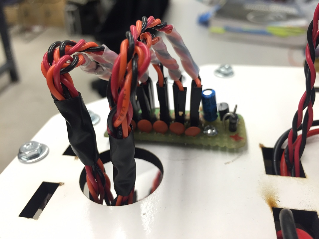
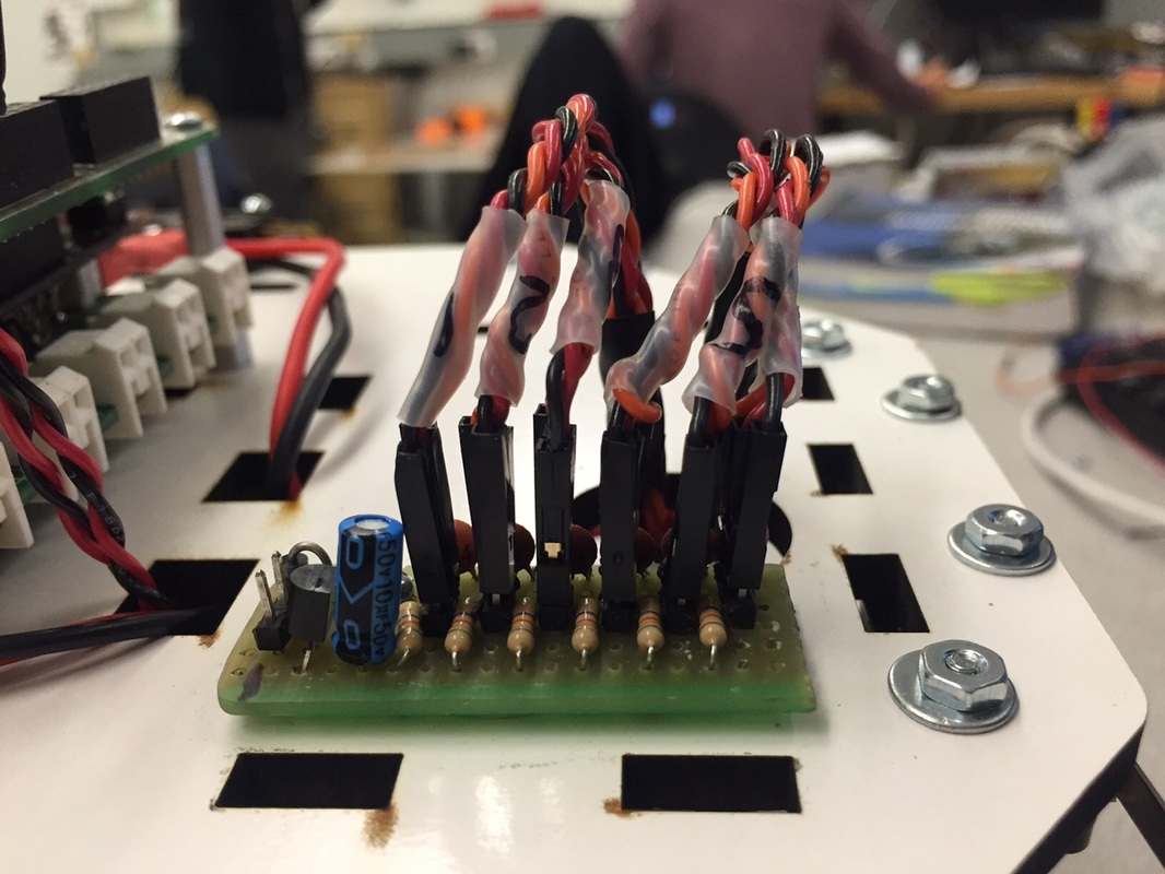
Beacon Detector Soldering
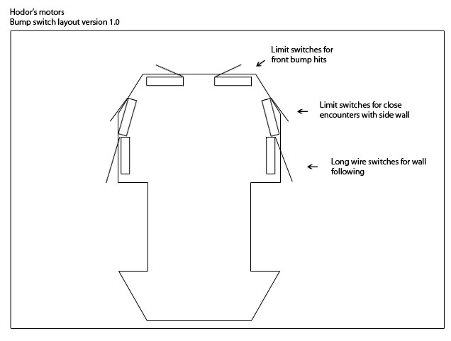
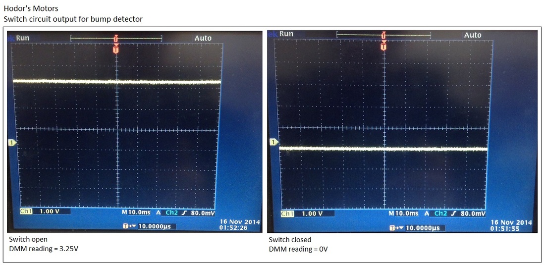
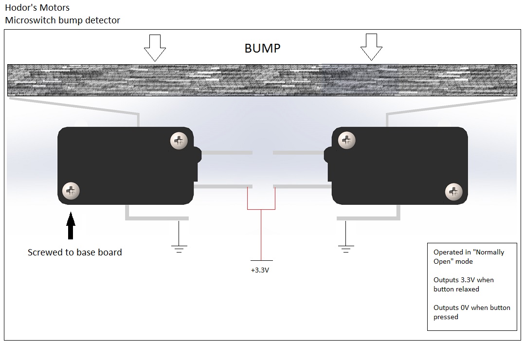
Front Bumper Sensor Response and Layout
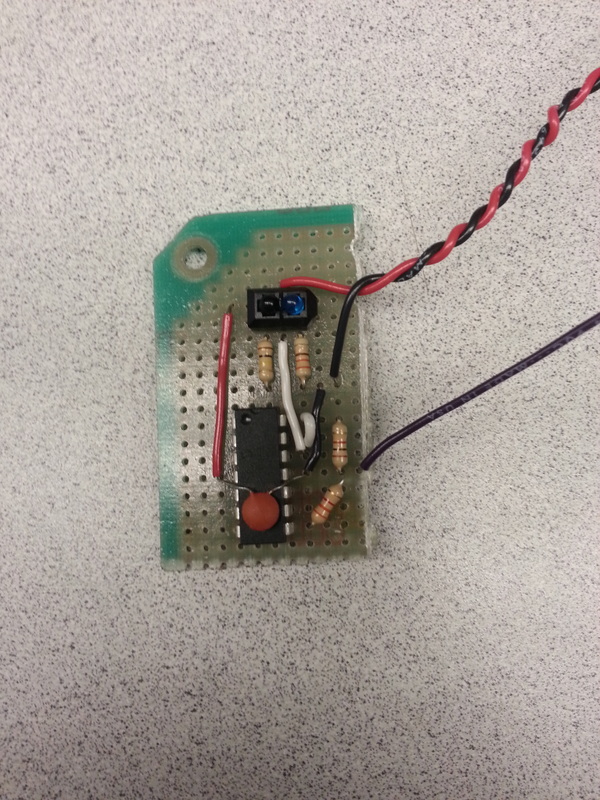
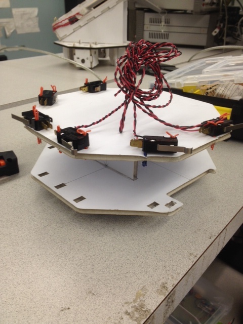
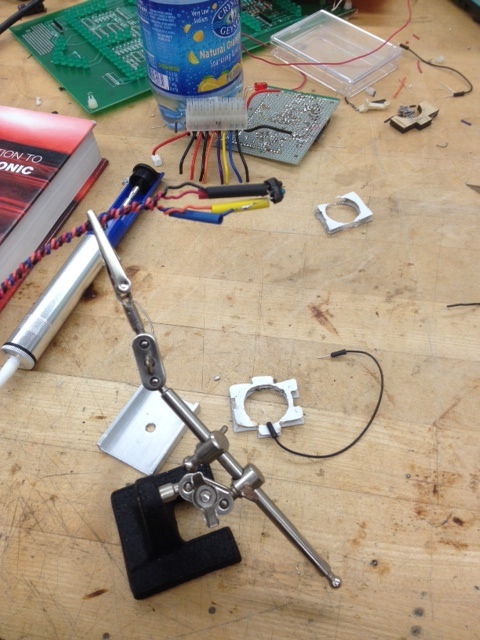
Tape Detectors Breadboard and Perfboard
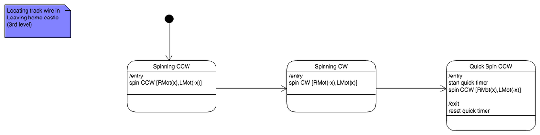
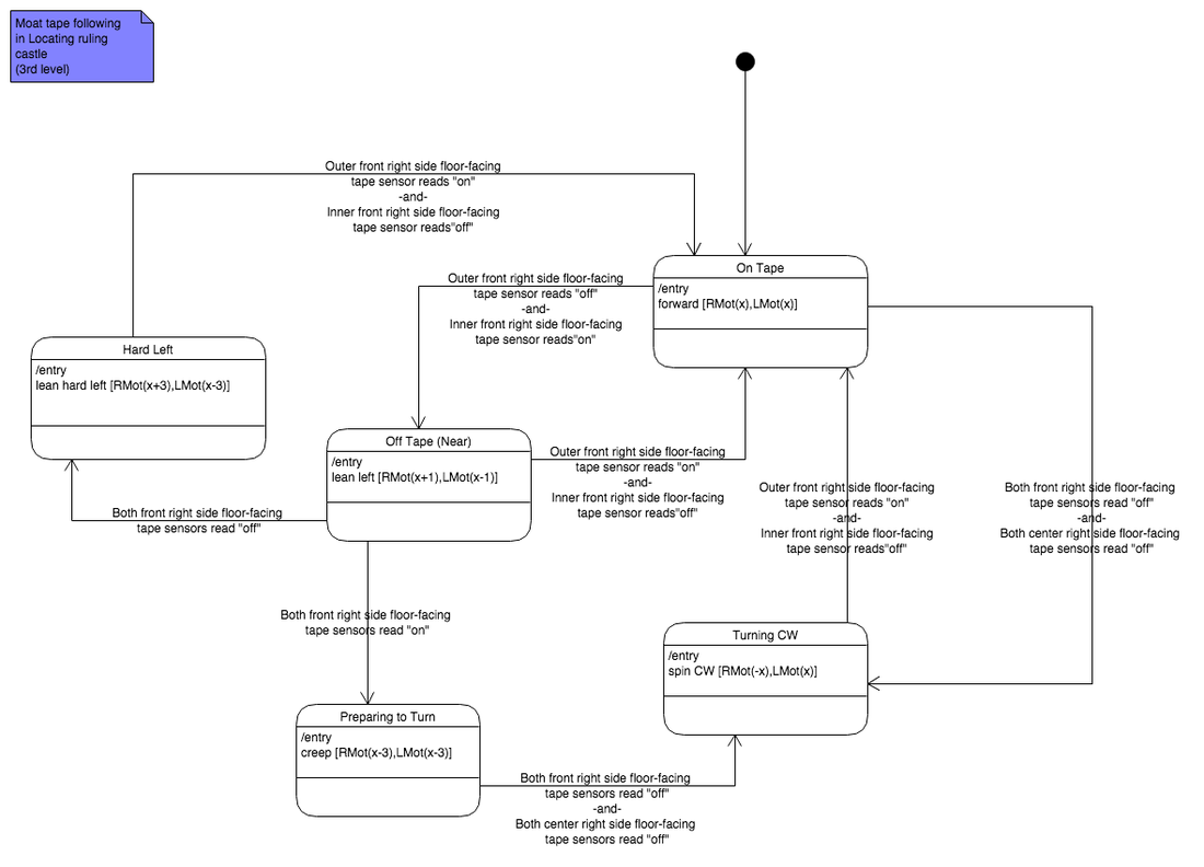
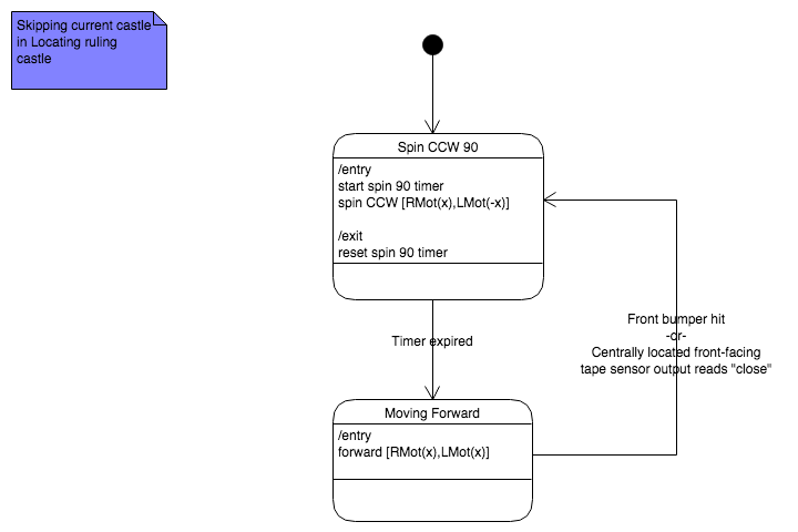
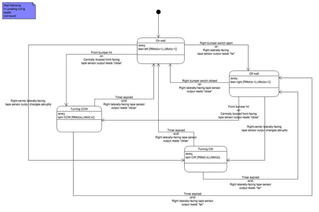
State Machine
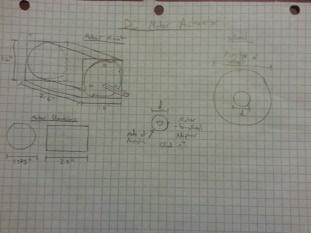
Actuator Schematics
Week 2 (Nov 18 - Nov 24)
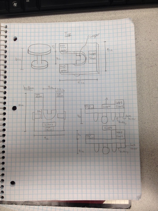
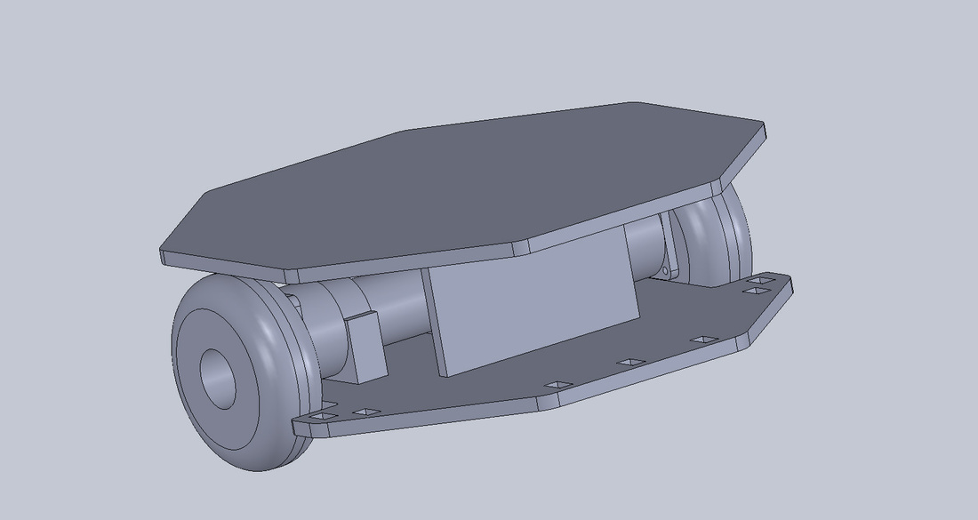
Solidworks design
Foam Core Prototype
Circuit for Bumper Switches
Using the 3.3V voltage regulator we are able to drop down the battery voltage to 3.3V to ensure that the bumper signal doesn't go higher than that and harm the UNO. The voltages across the resistors are the signals that are sent to the UNO. A bypass capacitor is used to stabilize the signal.
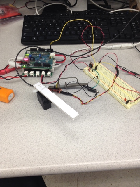
Tape Sensors
Visay TCRT5000L sensors were used for the tape sensors. Inside there is an IR emitting LED that we can drive at a certain frequency. The emitted light is reflected off of surfaces and detected by the phototransistor, from which we can read a voltage that corresponds to light intensity, depending on the reflecting material.
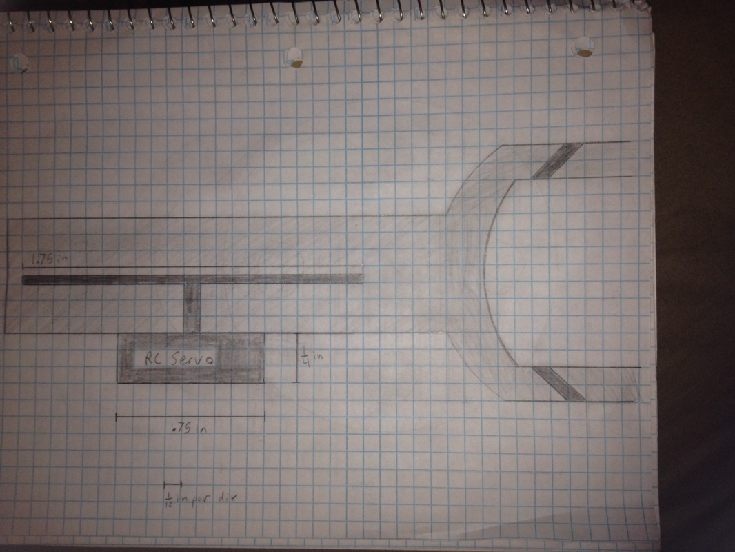
Interfacing to the RC Servo
The battery gives 9.9V which is distributed by the distribution board on the bottom. The breadboard uses a 7805 voltage regulator to create a 5V rail used to power the Servo. The UNO was programmed to output a pulse width of 1-2ms through PORTZ09 to the Servo. This was sent to the breadboard first so that we could probe the signal with the oscilloscope.
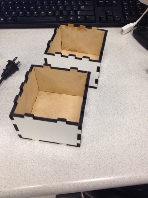
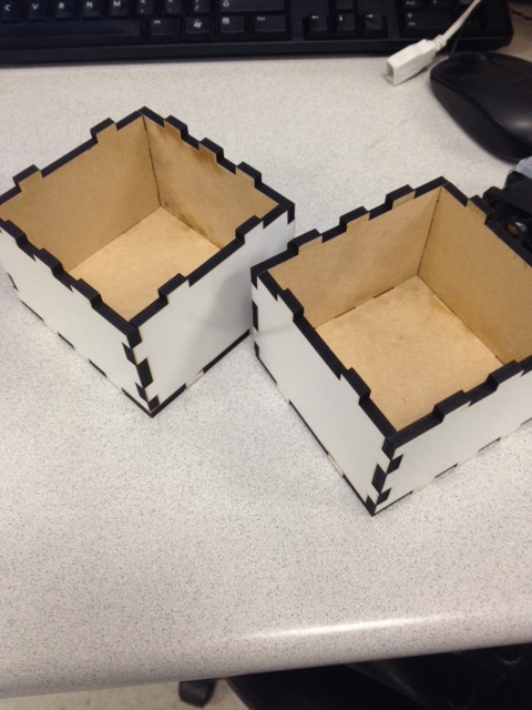
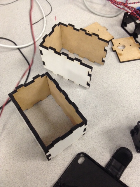
MDF prototyping
Enclosures are for UNO, H-Bridge, beacon detector, and other circuits.
Week 3 (Nov 25 - Dec 2)
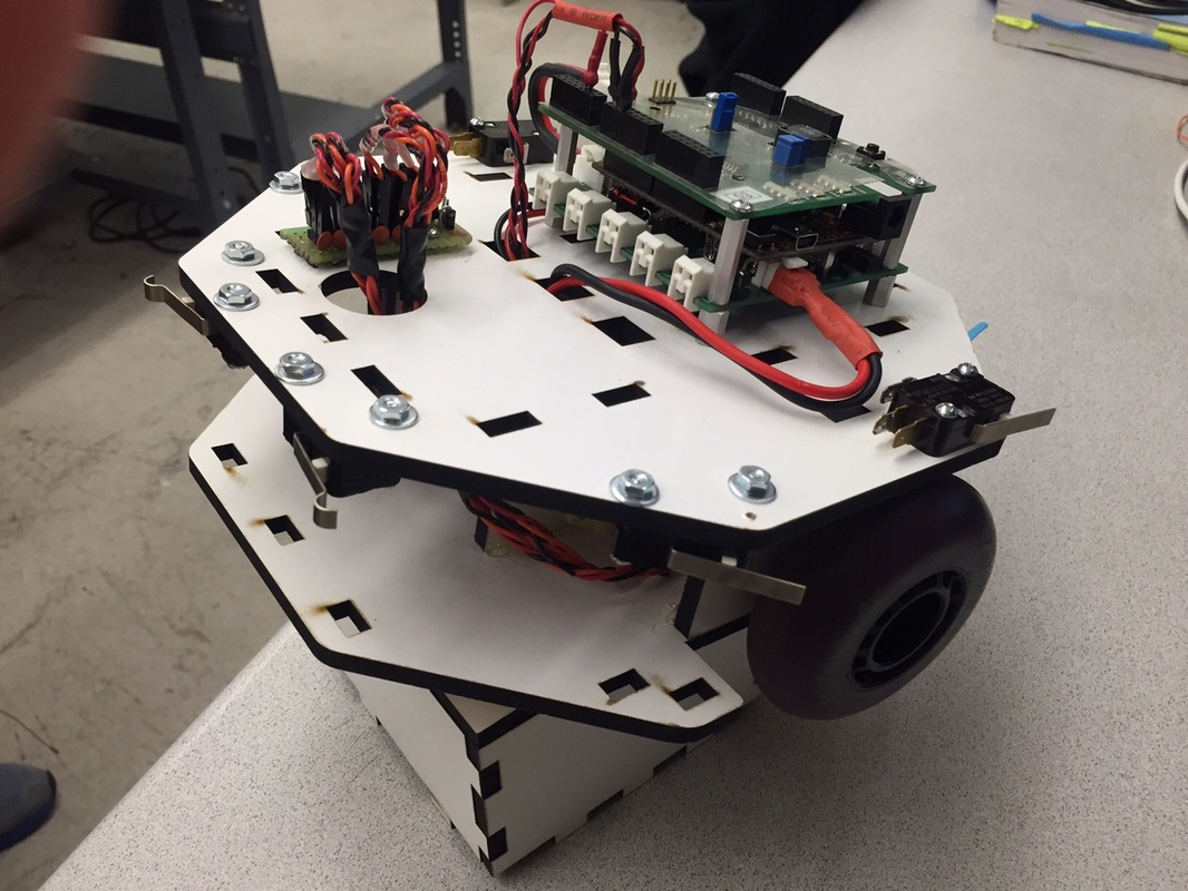
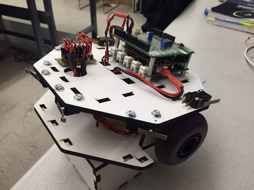
Assembled Prototype
We partially assembled our prototype to test for bump events, and have it respond with movement.
Improved Bumper Circuit
A protection diode was put in place after the Voltage Regulator was reversed biased, and stopped working. High pass filters were implemented by adding a capacitor from the output signal to ground. This greatly reduced noise, and we saw clean transitions down at the microsecond scale.
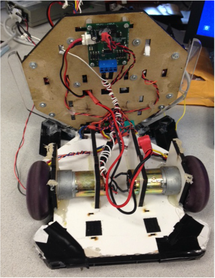
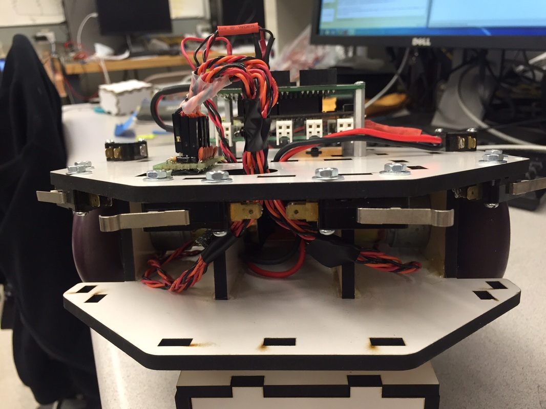
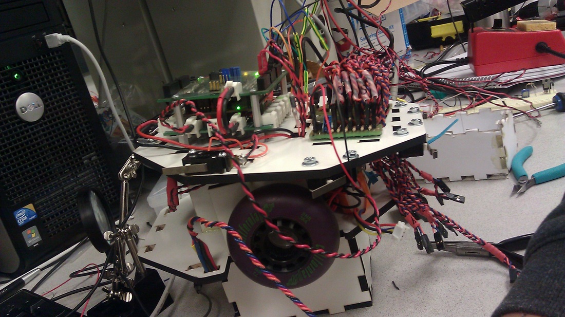
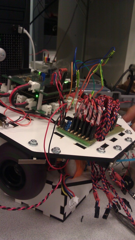
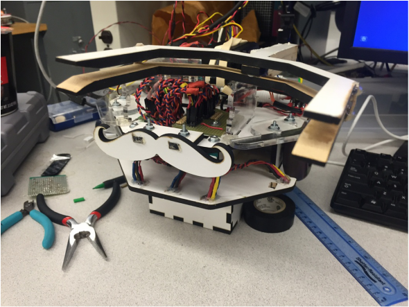
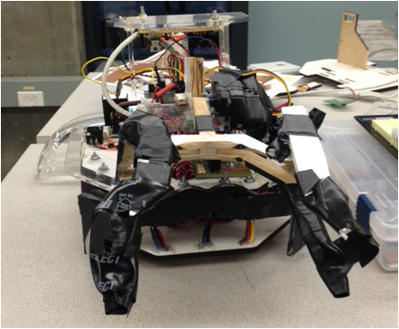
All Wired Up
This is what our robot looked like after we added in all the sensors.
Week 4 (Dec 3 - ...)
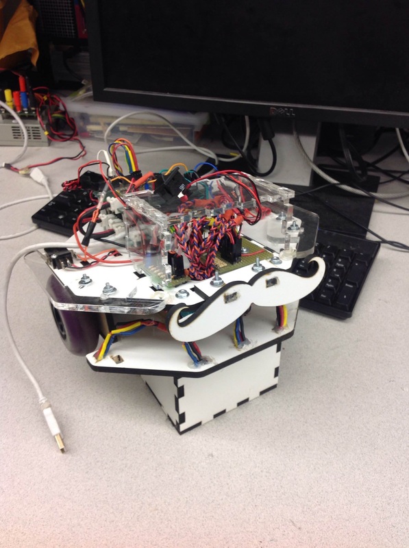
Acrylic Bumpers
We added in acrylic bumpers for the left and the right side and an mdf prototype Mustache bumper for front bumps. We also have an acrylic housing for the bumper and tape detector circuits.
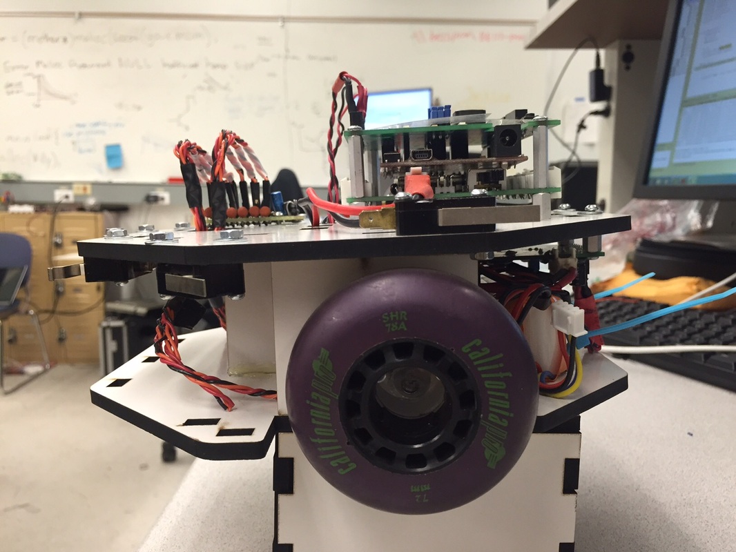
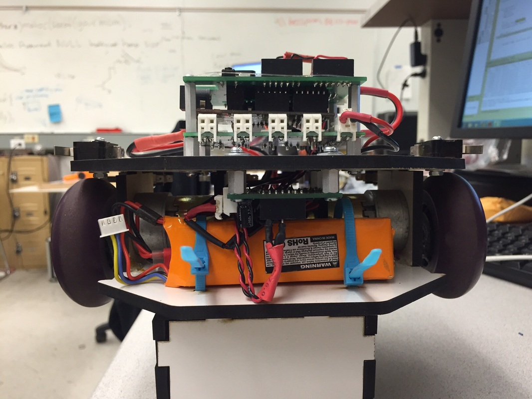
Another view
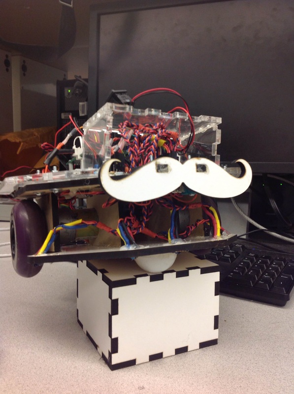
And another view...
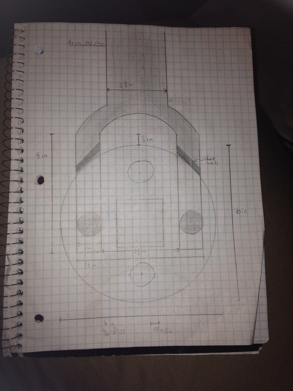
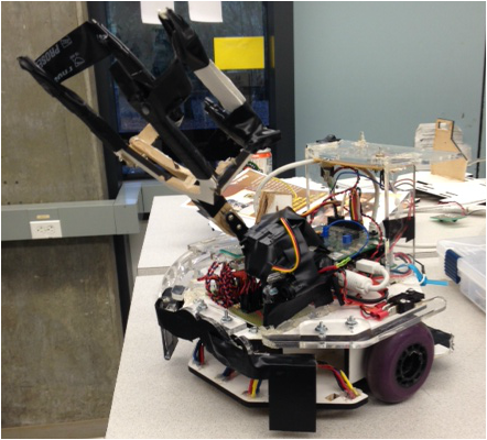
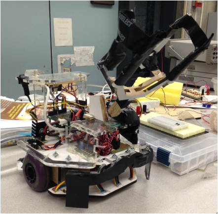
Arm prototype
We attached our arm prototype to the servo and started making it move up and down to simulate the crown grabbing motion. The height of the arm when it is horizontally level is just barely off of the desired height for it to reach the crown.
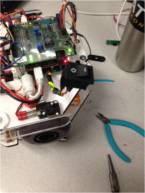
Remote Switch
The remote switch was connected to a 3 pin header on the power distribution board. To turn on the board we need to short either of the outer pins with the middle pin. The switch shown was used to create this short.
Bump Events
We integrated the bumpers and the motors so that we could drive forward and respond differently to the left, front, and right bumpers.
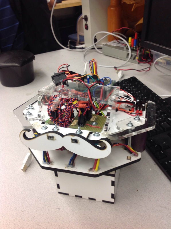
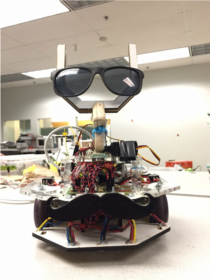
Working Design
Our cool looking robot, ready for the competition!
Grabbing the Crown
We are able to successfully pick up the crown. We are trying to figure out how to get back after this. Unfortunately we ran into problems that slowed us down. But we were able to make it work back to what we had it again. Right now some of our timers are off and they are messing us up on some of our turns.
Tape Avoidance
In this run we had added in the capability to avoid tape while the robot moves down the hallway. It corrects itself by first stopping, then driving slightly to the left. In the video we see that the robot bugs out when it hits the front wall. What it is supposed to do is hit the wall, backup, do a 180 while it looks for the beacon, and then align itself with that same wall. There was an error in the code when we ran this, but it was fixed after the video was taken.
Final Design
This was our final design. It involved a lot of tape and a lot of hot glue. Near the end we started working mainly on the software and we modified the hardware as we saw fit to make it work. The arm was supposed to be a quick prototype, but after we saw it working pretty well, we decided to keep it and reinforce it with black electrical tape.
|
|
We took it apart
We had to remove the UNO stack, the H-Bridge and the battery so that we could return them.